| UPS structure
Generally, the UPS model is structured in one of three off-line, interactive and on-line modes. |
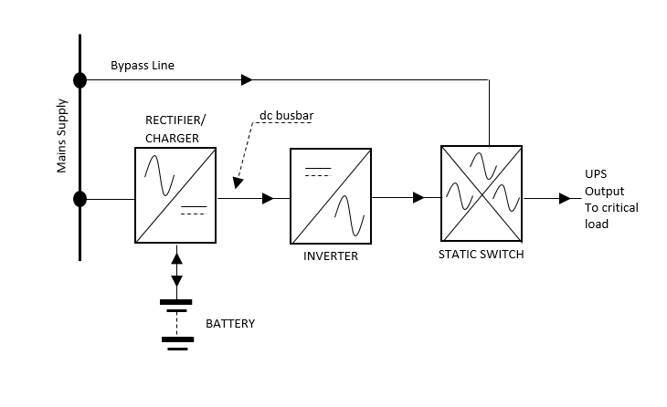
| Regardless of the specific design of each, several important features are common to all UPSs, all of which have batteries and store energy in batteries as long as city electricity is available and after alternating power outages the city supplies battery power. (AC) convert. Therefore, as shown in the figure below, all systems must have a battery charge and an inverter circuit.
According to the above explanation, when the city has power failure, the battery acts as the inverter’s power source and is discharged at a rate that depends on the amount of charge consumed by the UPS. When the battery voltage drops below a certain level, the inverter automatically switches off, so the length of time the city can be charged depends on the battery capacity and the percentage of charge applied to the UPS. Typically in UPS systems, there are a number of batteries with proper servicing capacity to supply full load power for 5 to 15 minutes. However, in most cases this time can be increased by adding additional battery cabinets or selecting higher capacity batteries. Back-up time is also often referred to as Autonomy. Essentially, “all UPSs have a bypass system that, along with an on-board switch, provides the charge for direct power supply to the city. In many cases, the output switch circuit is supplemented by the use of static switches. The static switch is plotted in the block diagram above, but in low powered devices this is done by relays.The principles of static switch control depend on the way the UPS works.
|
